- Navigating the DTC
- Tab Up & Tab Down
- Scroll Up & Scroll Down
- Enter/Exit
- Delete
- Setting the Contrast
- Auto/Hand Switch
- Programming a Chelsea Switch
- Adding a relay to a switch button
- Copying Switch Programming
- Button Modes
- On Mode
- Off Mode
- Toggle
- Mix Mode
- Maintain
- Group#
- Setup Menu
- Buttons 7 & 8 Special Functions
- Btns1-6 <- 9-14
- Btns1-3 <- 9-11
- Disable 1-6
- Disable 1-14
- 9-14 disables 1-6
- Digi-link Cards
- Groups
- Group types
- Momentary On
- Momentary Off
- Momentary Mix
- Maintain
- Maintain + Timer
- Maintain + Blink
- Overriding Groups
- Deleting Groups
- Group Toggle
- Global Groups
- Zones
- Changing from discrete to zone mode
- Adding or remove relays from a zone
- Schedules
- Schedule Types
- Every Day
- By Day
- Monday-Friday
- Schedule Control Methods
- Time Based
- Photocell
- Astronomical
- Setting up Holidays & Exceptions
- Disabling or Deleting a Schedule
- Photocells
- PCC1 and PCC3
- Disabling PCC Inputs
- Adjusting Input Sensitivity
- Blue Box Onboard Photocell
- MicroPanel Photocells (iDIM/iDH)
- Micropanels
- Activating a Scene
- Scene Types
- Raise
- Lower
- Scene
- Freeze
- No Auto
- Restart
- Flip
- MicroPanel Photocell Setup and Operation
- System Setup
- Setting Location
- Setting Date & Time
- Relay Properties
- Bus Map (Panel/Switch Types)
- Address by Button
- Keyboard Lock Code & Backdoor Password
- Troubleshooting
- Manual Override
- Read Address
- Bus Scan Display
- Scan by Serial
- What & When
- Schedules Events
- What Controls Groups?
- What Controls Relays?
Navigating the DTC
Tab Up & Tab Down
The TAB UP and TAB DOWN keys are used to move the cursor forward and backwards across the display. They change which parameter on the screen is selected.
Scroll Up & Scroll Down
The SCROLL UP and SCROLL DOWN keys are used to adjust the selected parameter. They are also used to override groups, copy switch programming, and disable or enable selected schedules. Scrolling up or down on a page number will bring you to the next page on the screen.
Enter/Exit
The ENTER button enters into the selected sub menu. It is also used to toggle loads from the manual override screen, and add loads into a switch or group. The EXIT button brings you back to the previous menu.
Delete
The delete key is used to delete groups and schedules.
Setting the Contrast
To set the contrast on the GR2400, hold the CONTRAST key, and then press SCROLL UP or SCROLL DOWN. To adjust the contrast on a Blue Box, there is a contrast adjustment screw on the back of the DTC.
Auto/Hand Switch
The Auto/Hand switch can be set to HAND to close all relays in the panel. This is useful for testing relays, and verifying line voltage is present on the relays. The panel must be in AUTO mode under normal operation.

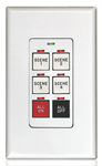
Programming a Chelsea Switch
Adding a relay to a switch button
To add a relay to switch button, enter into PROGRAM SWITCH from the USER MENU. Press ENTER on the switch ID# you wish to program, and then press ENTER on the button number you wish to program (buttons are numbered left to right, top to bottom). The mode of the button is selected in the top right hand corner of the button’s display (TOGGLE in this following image):

Select the correct LCP number (panel number), and LOAD number. Use SCROLL UP and SCROLL DOWN to adjust the LCP & LOAD numbers. Press ENTER on the load number to add it to the button. Added loads will appear in bold font, below the word “EDIT”. Press ENTER again on an added load to remove it.
Button Modes
SCROLL UP or SCROLL DOWN on the button mode to change it
On Mode
This mode will turn any relays added to the button ON.
Off Mode
This mode will turn any relays added to the button OFF.
Toggle
This mode will toggle (turn on and off) and loads added to the button.
Mix Mode
This mode is capable of turning some relays on and others off at the same time.
Maintain
This mode will hold the ON command, as long as the button is held down.
Group#
Assigning a group number, as a buttons mode, will make that button control the chosen group number. The button will use the group’s mode as the mode of operation.
Copying Switch Programming
To copy switch programming, enter into PROGRAM SWITCH from the USER MENU. Select the switch you wish to copy the programming from and press SCROLL UP. Then, select the switch you wish to copy the programming to and press SCROLL DOWN. Press ENTER on ‘Yes’ to confirm.
Setup Menu
The ‘Setup Menu’ is a special menu available on some switches, which allows the disabling of buttons, or the changing of a button’s function on the fly. You can access this menu by entering into PROGRAM SWITCH on the USER MENU, entering into a specific switch ID#, and then selecting SETUP and pressing ENTER. To use these features, the switch must be setup as a 14 button switch (see BUS MAP).
Buttons 7 & 8 Special Functions
7 ON = will perform the function you select, when a relay programmed to button 7 is on (assumes ON MODE)
8 ON = will perform the function you select, when a relay programmed to button 8 is on (assumes ON MODE)
Btns1-6 <- 9-14
This function will swap the functions of buttons 1-6 with the functions of buttons 9-14 respectively.
Btns1-3 <- 9-11
This function will swap the functions of buttons 1-3 with the functions of buttons 9-11 respectively.
Disable 1-6
This function will disable buttons 1-6 on the switch.
Disable 1-14
This function will disable buttons 1-14 on the switch.
9-14 disables 1-6
When this option is set to Y, buttons 9-14 can disable buttons 1-6. If the load programmed to button 9 is on, button 1 will be disabled. If the load programmed to button 10 is on, button 2 will be disabled and so forth (this assumes the button is programmed in ON MODE):
Button 9: RELAY ON disables Button 1
Button 10: RELAY ON disables Button 2
Button 11: RELAY ON disables Button 3
Button 12: RELAY ON disables Button 4
Button 13: RELAY ON disables Button 5
Button 14: RELAY ON disables Button 6
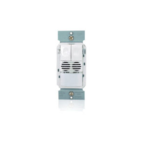
Digi-link Cards
A digi-link card is a contact closure card. It is programmed exactly the same as a Chelsea switch. A digi-link card can have either 6 or 14 inputs and therefore, is set up as either a 6 or 14 button switch. Each input on the card is represented as a button. When an input# becomes electrically connected to the local ground on the digi-link card, it triggers that input number.
Here is a diagram, demonstrating the wiring on the LC&D digi-link card:

Groups
Any relays that are going to be on a time schedule must be part of a group. When more than 8 relays are being added to a switch button, those relays must also be part of a group. Groups are useful when you have multiple switches that operate the same loads. You can assign a group to a switch or photocell, instead of having to assign every load individually. To create or edit a group, press ENTER on GROUP LOADS on the USER MENU. Select the group number you wish to edit, and press ENTER. You will a screen similar to this one.

To add loads to a group, use the same method as adding loads to a Chelsea switch
(see Programming a Chelsea Switch)
Group Types
Momentary On
This is similar to On Mode. When a group is set to Momentary On, that group will turn on whenever it is triggered.
Momentary Off
This is similar to Off Mode. When a group is set to Momentary Off, that group will turn off whenever it is triggered.
Momentary Mix
This is similar to Mix Mode. When a group is set to Momentary Mix, the group can trigger some relays ON, and others OFF at the same time.
Maintain
A group programmed as Maintain will stay on as long as it’s ON command is held. On a switch, the button has to be held down for the load to stay on. This is also the correct group type to use for loads under photocell and time schedule control.
Maintain + Timer
This group type is made to be used in conjunction with time schedules. When a Maintain+Timer group is scheduled on, the auto off timer will be disabled, and the lights will stay on. Outside the hours of its scheduled times, the group will time out and shut off after being on for a certain amount of time. If you press ENTER while you have this group mode selected, you can adjust the value of the timer by entering into the SET TIMER sub-menu (default is 2 hours).
Maintain + Blink
This group type is the same as a Maintain+Timer group, except the lights will flash before timing out to warn the occupant. If you press ENTER while you have this group mode selected, you can adjust the number of minutes, prior to shutting off, the lights will blink. This setting is also adjusted under the SET TIMER sub-menu. A 2nd blink warning can be programmed here as well.
Overriding Groups
To override a group, select GROUP LOADS from the USER MENU and press ENTER. TAB DOWN and select the group you want to override. SCROLL UP to override the group ON. SCROLL DOWN to override the group OFF.
Deleting Groups
To delete a group, select GROUP LOADS from the USER MENU and press ENTER. TAB DOWN and select the group you want to delete and press the DELETE key. Press ENTER on ‘Yes’ to confirm.
Group Toggle
Groups do not have a toggle mode. If you want to toggle a group, you have to use a spare status relay, and the button 7 & 8 special functions.
Global Groups
Groups 17-32 are preprogrammed to be global for all multi-bus systems. This means they will activate universally across all system busses whenever activated on any single bus. To take advantage of this feature, the global group must be set up identically on all system busses.
Zones
Zones are similar to groups, except a relay may only be assigned to one zone. Zones will only exist if a panel has been set up in zone mode, as opposed to discrete mode. Discrete mode is the normal mode for most systems. In discrete mode, Load 1 is Relay 1; Load 2 is Relay 2, and so forth. In zone mode, Load 1 is Zone 1; Load 2 is Zone 2, and so forth. Zones are programmed using the buttons on the control card. Changing the mode of a panel, from discrete mode to zone mode, is also done using the buttons on the control card.
Changing Panel Mode
To change the mode of the panel, press and hold the ASSIGN button on the control card. After three seconds, the relay LEDs will shut off. Continue to hold the assign button and press the following key sequence on the relay buttons:
2, 4, 6, 2, 6
Let go of the ASSIGN button. After about 5 seconds, the relays will change state. The panel has now cycled to the next mode. It cycles through the modes in this order:
-8 Zone Mode (Panel uses 8 zoned loads)
-16 Zone Mode (Panel uses 16 zoned loads)
-Discrete Mode (Panel uses a load for each relay)
…and then repeats
Adding or removing relays from a zone
To add or remove a relay from a zone, press the ASSIGN button, and then press the button for the zone number that you’d like to add or remove relays from. Pilot lights for all relays in that zone will light. Press the button for each relay number you’d like to add to, or remove from that zone. If the pilot light for that relay number flashes after you press it, it means that relay is already in a zone. Press the button again to force it into the zone. Leave it alone for 5 seconds, and the relay will not be assigned. Press the ASSIGN button again when you have added or removed all necessary relays to save the configuration.
Schedules
Schedules are used to set automatic on and off times for any relays inside an LC&D panel. They are also used to set up photocell schedules for the onboard photocell in a master Blue Box. To edit or view the existing schedules, select REVIEW SCHEDULE from the USER MENU and press ENTER. A column of schedules will appear on the left. What those schedules control will appear in the column on the right. The schedules (SCH 1, SCH 2…) contain the off and on times. The group to the right of a schedule, contains the relays that will turn on and off at those times. See the following screenshot:

Press SCROLL UP or SCROLL DOWN on a GROUP # or NO LOADS to change what group is controlled.
Schedule Types
Every Day
A schedule to set to EVERY DAY means that the schedule runs every day of the week, and does not change from day to day.
By Day
A BY DAY schedule is used when different on and off times are needed for different days of the week. Press ENTER on any day of the week to change the on and off times for that day. BY DAY schedules can also be set up to run within a certain range of dates. This range can be adjusted at the bottom of the BY DAY schedule screen.
Monday-Friday
A schedule set to Monday-Friday runs the same schedule Monday through Friday, but allows you to program separate on and off times for both Saturday and Sunday.

Pressing SCROLL UP or SCROLL DOWN on the word TIME, changes control method of that timed event.
Schedule Control Methods
Time Based
When a schedule displays ON TIME, or OFF TIME, it is switching on or off its group at a particular time. This is the default control method for a schedule. The ON TIME indicates what time the schedule will turn its group on. The off time indicates what time the schedule will turn its group off. The time set on the controller is displayed on the start screen.
Photocell
When a schedule displays ON PCEL or OFF PCEL, it is switching based on a photocell. The ON PCEL time indicates what time the onboard photocell, in a BlueBox, is going to start controlling the group. At the OFF TIME, the lights sweep off, and the photocell relinquishes control of the group. If you have the word PCEL selected, and you press ENTER, you will see this screen:

ANALOG1 shows the current value that the onboard photocell is reading. TIME DELAY is how long the photocell must remain past the triggering levels, before actually switching the loads. ON WHEN LEVEL FALLS BELOW will turn the loads on when the lighting level read by the photocell is under the set value. OFF WHEN LEVEL RISES ABOVE will turn the loads off when the lighting level read by the photocell is above the set value.
Astronomical
When a schedule displays ON DUSK, ON DAWN, OFF DUSK, OR OFF DAWN, it is switching its group according to an astronomical clock. Using this method, the controller will use the longitude and latitude entered in its SYSTEM OPTIONS, to calculate the DUSK and DAWN times. DAWN indicates the time that the sun sets. DAWN indicates the time that the sun rises. The times that the controller calculates dusk and dawn to be, will flash periodically on the start screen of the system controller.
Setting up Holidays & Exceptions
By default, schedules are set up with no exceptions (EXCEPT NONE). An exception is a day of the year, in which the schedule does not run. To set up an exception, the day you would like to exempt must be entered into a holiday list. To do this, enter into the SETUP MENU from the USER MENU. Select SYSTEM SETUP MENU and press ENTER, and then select EDIT HOLIDAYS and press ENTER. Enter into either holiday list. Pages 1 & 2 of the holiday list have predefined, commonly used holidays. Pages 3 & 4 have dates that you can adjust yourself. To make a day in the holiday list active, scroll on NO next to the day and change it to YES:

After you have set the day to YES in the HOLIDAY LIST, scroll on EXCEPT NONE in the schedule screen to change it to EXCEPT H1, EXCEPT H2, or EXCEPT H1+H2. Using EXCEPT H1 will exempt any active days in HOLIDAY LIST 1. Using EXCEPT H2 will exempt any active days in HOLIDAY LIST 2. EXCEPT H1+H2 will exempt activate days on both holiday lists:

Disabling or Deleting a Schedule
To disable a schedule, enter into REVIEW SCHEDULE from the USER MENU. Select the schedule you would like to disable and press SCROLL DOWN. The display will read ‘Disabled’ where the group normally appears to indicate the schedule is now disabled. To re-enable the schedule, select the schedule and press SCROLL UP.
To delete a schedule, enter into REVIEW SCHEDULE from the USER MENU. Select the schedule you would like to delete and press the DELETE key. Press ENTER on ‘Yes’ confirm.
Photocells
PCC1 and PCC3
PCC1 & PCC3 cards are photocell input cards. A PCC 1 card is a single input card that and a PCC3 card is a 3 input card that can be digitally disabled. PCC cards read the light level from a 2-wire analog photocell, and communicate the reading back to the system controller. To program a PCC card, select PROGRAM SWITCH from the USER MENU and press ENTER. Select the ID# of the photocell card and PRESS ENTER (PCC cards will appear as ANALOG/DIGI in the PROGRAM SWITCH screen). You will see a list of triggers.
PCC cards are programmed using triggers. A trigger defines two things: The lighting levels at which the loads will turn on and off, and which loads are being triggered at those levels. To program a trigger, select a TRIGGER# and press ENTER. Here you can enter which loads are to be controlled by that trigger the same way you would enter loads into a Chelsea switch (see Programming Chelsea Switch).
The mode of the TRIGGER will appear in the top right hand corner of the trigger screen. The default mode is MAINTAIN. If you press enter while the mode is selected, you can adjust the on and off triggering levels:

If you press SCROLL UP or SCROLL DOWN while ANALOG is selected, you can choose which input number on the PCC card the trigger is referencing. In the image above, input #1 on the PCC card is reading 32. TIME DELAY indicates how long the photocell must be beyond the triggering points before it will switch the loads. You can SCROLL UP or SCROLL DOWN on the on and off triggering levels to adjust them here as well.
Disabling PCC Inputs
On a PCC3 card, inputs 1-3 are disabled using triggers 11-13. If a load programmed to trigger 11 is ON, trigger 1 is disabled. If a load programmed to trigger 12 is ON, trigger 2 is disabled. If a load programmed to trigger 13 is ON, trigger 3 is disabled. This assumes triggers 11-13 are programmed in ON MODE.
Adjusting Input Sensitivity
Below each photocell input on a PCC3 card, is a dial that can be adjusted to change the sensitivity of that input. Turning the dial clockwise will decrease the sensitivity of the input to work better outdoors. Turning the dial counter clockwise will increase the sensitivity of the input to work better indoors.

Blue Box Onboard Photocell
See Programming Schedules: Photocell Control
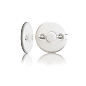
Micropanel (iDIM/iDH) Photocells
If an LC&D system uses a photocell hooked up to a MicroPanel, the photocell may only control loads from within that MicroPanel. The Micropanel photocell is a 3-wire photocell and it is wired to the control card as shown below:

For more information on programming MicroPanel photocells, see MicroPanel Photocell Setup & Operation
MicroPanels
Controlling a MicroPanel is accomplished through Scenes. Scenes are presets, which determine how the lighting loads are controlled. A MicroPanel may contain up to 12 scenes, which are represented by loads 5-16 on the MicroPanel. There are two types of MicroPanels: the iDH, and the iDIM. The iDH does not contain 0-10v dimming outputs and therefore can only be used for switching. The iDIM does contain 0-10v outputs, and is capable of daylight harvesting.
Activating a Scene
Turning on a scene can be done through the manual override screen, schedules, Chelsea switches, or through the hardware inputs on the control card of the MicroPanel. The image below shows how you can activate scenes, using various dry contacts attached to the hardware inputs:

If any scene input is electrically connected to GND, that scene number will activate. By default, the input is considered a MAINTAIN type, and will only keep the scene on for as long as the contact is connected. Inputs can also be programmed to work as a momentary contact (see Relay Properties)
Scenes
If you press ENTER on iDIM/iDH Scenes on the USER MENU, you will see a display similar to this one:

Each item here is a scene. You can select a scene and press SCOLL UP or SCROLL DOWN to change the type of the scene. The type of the scene will indicate what the scene does when it is activated. You can also SCROLL UP or SCROLL DOWN on the LCP number to change which MicroPanel you are programming. If you press ENTER on a scene, a display will appear with the settings for that scene:

In this image, DIM1, DIM3, & DIM4 are the 0-10v outputs (outputs 1, 3, & 4). Typically you will see these types of channels on an iDIM panel. Rly2, Rly5, Rly6, Rly8, & Rly7, are the relays in the MicroPanel. Typically you will see these types of channels on an iDH panel. Next to each of these relay and dimmer channels, the preset level is listed. You can adjust this using SCROLL UP and SCROLL DOWN. PC here, indicates a photocell will determine the level of that output when the scene is activated. ON indicates the relay will turn on when the scene activates. N/A indicates no change will be made to that channel when the scene is activated. DIM channels can also be set at levels between 0% and 100%.
If you press ENTER while PC is selected it will take you to the photocell setup screen. (See MicroPanel photocell Setup & Operation for more info)
Here is a list of the most commonly used scene types in a MicroPanel and their functions:
Raise
A scene set to RAISE, will raise any dimmer channels that are set to RAISE inside of the scene. Use a MAINTAIN type contact for this scene type. Holding down the contact will slowly raise the level of the dimmers. If the contact is double tapped, the output will increase to full brightness. This scene has an adjustable FADE rate, which is the amount of time the dimmer channels take to go from 0 to 10 volts.
Lower
A scene set to LOWER, will lower any dimmer channels that are set to LOWER inside of the scene. Use a MAINTAIN type contact for this scene type. Holding down the contact will slowly lower the level of the dimmer. If the contact is double tapped, the output will decrease to minimum brightness. This scene also has an adjustable FADE rate, which is the amount of time the dimmer channels take to go from 10 to 0 volts.
Scene
A scene set to SCENE, can set any channel to operate off of a photocell, or maintain a certain level of brightness between 0% and 100%. Like most scenes, this scene can also command relays ON and OFF.
Freeze
A freeze scene will lock a certain scene in place for a set time period, and then return to the original scene. During this time, any occupancy sensors or photocells controlling loads in the FREEZE scene will be disabled.
No Auto
The NO AUTO scene is a scene that will not turn on from a locally wired occupancy sensor if the scene is turned off. The occupancy sensor, however, will always be able to sweep the lights off.
MicroPanel Photocell Setup and Operation
If you have a DIM channel set to PC, and you press ENTER while PC is selected, you will see this screen:

You can SCROLL UP or SCROLL DOWN on IN1 here to select a different photocell input for that channel to reference. FADE UP and FADE DN are the amounts of time it will take for the dimmer to sweep along the full dimming range up and down respectively. START indicates the light level where the channel starts to dim. MID indicates that lighting level where the dimmer will output 50%, and OFF indicates the lighting level at which the channel will turn completely OFF. If the brightness is above the MUST Turn ON level, the channel will turn on regardless of the fade times. Time Out from Off is the amount of time after the dimmer has turned off before it will turn on again.
Restart
The restart scene is made to be used with photocells. It will periodically re-initialize itself, and reassert photocell control over any channels set to “PC” inside of the scene. The time between each re-initialization is determined by the TIMER value inside of the scene. The scene will only adjust channels that have been raised above the light level deemed appropriate by the photocell. If any channels are manually dimmed below this level, a restart scene will not raise them when it re-initializes. If you would like it to, you must change ReStart to ReIterate in the top right hand corner of the scene.
When a ReStart scene is turned off its behavior will depend on the setting in the lower right hand corner of the scene display. If NO-OFF is listed at the bottom of the scene, photocell control remains on, but the scene stops re-initializing periodically. You can change this setting to OFF-OK, in which case the channels will actually turn off when the scene is turned off, as opposed to allowing photocell control.

Flip
The flip scene is a special scene that allows you to switch back and forth between two different scenes, as opposed to just having a single scene turn on and off. Only scenes 5-10 can be set up as flip scenes, because they swap with scenes 11-16 respectively when triggered.
There are two different triggering modes for a flip scene. They are trigger by INPUT and trigger by RELAY. Whichever mode is being used will be displayed in the top right hand corner of the scene:

Trigger by INPUT means that the state of the contact closure input determines which scene is being used. If scene 5 was set up as a flip scene, a contact closure on the scene 5 input would turn on scene 5. When the contact opens, scene 11 is activated.
Trigger by RELAY uses the status of scenes 5-10 in the manual control screen to determine which scene is being used. If the scene 5 status is ON, scene 5 is used. If the scene 5 status is OFF, scene 11 is used. The statuses of scenes 11-16 are used to turn the associated flip scene on and off. Scenes 5-10 may ONLY be operated from the bus when using this mode.
System Setup
Restricted
The restricted menu is a password protected menu that contains additional system options. You can access the restricted menu through the SETUP MENU. The password is 900001.
Setting Location
The location setting is used to calculate dusk and dawn times when using the astronomical clock for time scheduling. You can change this setting through the SETUP MENU -> SYSTEM SETUP MENU -> SYTEM OPTIONS -> SELECT LOCATION. There is a preset list of cities here that you can select as your location, or you can manually enter your longitude and latitude. Press ENTER while ‘HIT ENTER’ is selected to save your changes at either of these menus.
Setting Date & Time
You can change the current date & time setting on the controller through the SETUP MENU -> SYSTEM SETUP MENU -> SET DATE AND TIME. Press ENTER while ‘HIT ENTER’ is selected on this screen to save your changes.
Relay Properties
You can access the Relay Properties screen through the SETUP MENU. At this screen you can change a relay from normally closed, to normally open. You can also adjust the automatic off timer and blink warning timer for a relay, or disable blink functionality on a relay. When you first enter the Relay Properties screen you will see this display:

Each board here represents 8 relays. The board number is the address associated with those eight relays. In the above example, there are two 16 relay panels. One panel is addressed at 1 and the other is addressed at 5. 16 relay panels take up 2 addressed each. Press ENTER on a board number to view the 8 relays at that address, and their properties. Screenshot is on the next page.

The above image shows the first 8 relays out of the control panel at address 1. If this were a 16 relay panel, the next 8 relays would be accessible from board 2. Each relay’s settings are in the same column as the relay number. In this image, relays 1, 2, 3, & 4 are set to normally closed, with the blink warning disabled for those relays. You can scroll up or down here on a relay setting to change it from ‘Y’ to a dash and vice versa. Pressing ENTER on any Y or dash setting here will also allow you to disable or adjust any timers on the associated relay. If the associated relay represents a scene in a MicroPanel, you will also have the option to change the input type to MAINTAIN, MOMENTARY, or TOGGLE.
Bus Map (Panel/Switch Types)
The Bus Map is where the CAT5 network map is stored. It contains a list of every address on the system, and what type of device is at that address. For almost any device on the CAT5 bus to operate properly, it must be entered into the Bus Map with its correct address and device type. The Bus Map can be accessed through the Restricted Menu. Device types can be changed using SCROLL UP and SCROLL DOWN.
Address by Button
Located somewhere, on every LC&D network device, is an address/assign button. This button can be used to address the device from the system controller. To do this, access the ADDRESS BY BUTTON menu from SETUP MENU -> SYSTEM SETUP MENU -> ADRESSING BUS SCAN -> ADDRESS BY BUTTON. Press SCROLL UP and SCROLL DOWN to change the address number:
. 
Once you have the desired address number set, press the address button on the device you want to assign that address to. The address number displayed will auto-increment to indicate the address has been assigned to the device.
Keyboard Lock Code & Backdoor Password
The controller can be configured with a lock code to restrict access. This code can be entered through SETUP MENU -> SYSTEM SETUP MENU -> SYSTEM OPTIONS -> KEYBOARD LOCK CODE. Setting this code to 0000 will disable the lock code completely. If a user forgets the password, the backdoor password of 5556 will always work.
Troubleshooting
Manual Override
The manual override screen is accessible through the main USER MENU. It is used to manually turn loads on and off. This screen will also tell you which loads are on, which loads are off, which loads are in the process of timing out and which loads have been issued blink warnings.

The numbers at the bottom represent all the loads within the selected panel (LCP1 in this image). If you press ENTER on a load number here, that load will toggle. A darkened box next to the load number indicates that the load is on. A dash indicates that it is off. A box with a single leg means that the load is timing out. A box with two legs means that the load has been issued a blink warning.
Read Address
Located somewhere, on every LC&D network device, is an address/assign button. In addition to being able to use this button to assign an address to the device, you can also use this button to read the currently assigned address from the device. To do this, access the READ ADDRESS menu from SETUP MENU -> SYSTEM SETUP MENU -> ADRESSING BUS SCAN -> READ ADDRESS. Press the address button on the device you wish to read the address from. Its address and serial number will be displayed on the screen.
Bus Scan Display
The bus scan display gives a visual representation of all detected system devices on the CAT5. This menu can be accessed through SETUP MENU -> SYSTEM SETUP MENU -> ADRESSING BUS SCAN -> BUS SCAN DISPLAY. Each digit on this display represents a system address. The addresses run left to right, top to bottom, and there are 127 total addresses. Panels are shown here as 3’s, and switches appear as 1’s. In the following display there is a panel at addresses 1 and 2. There is a switch or similar type device at addresses 4 and 5:

Scan by Serial (Scan by Factory ID)
Scan by Serial is a function that will scan that CAT5 bus, and return a list of all detected devices, their serial numbers, and address numbers. After scanning, it also informs you if there are any unaddressed devices or duplicate addresses (collisions) and allows you to reassign device addresses. This is useful because it allows you to address switches and other devices without having to physically be present at the device. Scan by Serial can be accessed through RESTRICTED -> ADDRESSING BUS SCAN -> MORE DIAGNOSTICS -> DEVICE MANAGEMENT -> SCAN BY SERIAL. After pressing ENTER on Scan by Serial, you will see this screen:

Press ENTER to resume and the system will show total items, collision count, and unaddressed item count.

Pressing ENTER again here, will bring you to the list of devices on that CAT5 (see image on the next page)

Pressing SCROLL UP or SCROLL DOWN while the Serial # is selected will allow you to cycle through all the CAT5 devices by their serial numbers. Unaddressed devices will come up here with an address of zero. To change the address of a device, select the address number and press SCROLL UP or SCROLL DOWN to set the desired address. Select “SAVE ADDRESS CHANGES”, and press ENTER to save any address changes made at this screen.
What & When
The What & When menu has 3 sub menus:
Scheduled Events
This will display a list of upcoming scheduled events in the time schedule. It gives you details about the events, such as the group number, the time, and whether it is an ON or OFF event.
What Controls Groups
This will tell you what controls a specific group number. If you select a group here and press ENTER, it will list any switch buttons or schedules that control that group.
What Controls Relays
This screen will tell you what controls a specific relay. If you press ENTER on a load number here, it will tell you what switch buttons operate that relay. It will also tell you if that relay is part of a group, and display the group number.