3 Things We Love About Acuity’s nLight
As a controls and lighting company, Lite Rite Controls is often asked to bid jobs that have nLight as the Commercial Building Lighting Control Systems. For those of you not familiar with nLight, I have added a brief description below of both nLight and nLight Air.nLight is a networked digital lighting control system that provides both energy savings and increased user configurability by cost effectively integrating time-based, daylight-based, sensor-based and manual lighting control schemes. nLight creates an unmatched level of distributed intelligence.
nLight Air is a secure, high-performance wireless platform designed for integration into various lighting controls applications that seamlessly connect both indoor and outdoor lighting systems to Smart Building Ready solutions.
Benefits Include:
- Easier installation – fixture embedded smart sensor remove guesswork, saving time and money
- Industry leading 5-tier wireless security architecture
- Energy savings with occupancy and daylight sensing — up to 30% additional energy savings
- Aids in meeting and/or exceeding state and local energy codes
- A scalable and upgradeable smart building ready solution
- Choose from a wide range of nLight AIR wireless enabled fixtures from Acuity Brands
Check out this nLight Video: https://www.youtube.com/watch?v=jXlGJvN9x4Q
Renpeng Zhang, a Lite Rite Controls employee and recent graduate from Long Beach State University, recently attended training on Acuity nLight products. Renpeng has experience programming and designing many different commercial building control solutions currently on the market and I wanted to find out what his thoughts were on the nLight product.
Jerimiah Hubner Lite Rite Controls (LRC): How did the nLight training go?
Renpeng Zhang (RZ): Yeah, it went really well. I liked that nLight is completely customizable. The training was very hands on, which I enjoyed.
LRC: That’s cool. Can you tell me about nLights customizable features?
RZ: Well, there are more customizable control features for commercial building control systems. One of the features is the “grace period” timing controls*. This controls how much time the occupancy/vacancy sensor takes before turning off lights or plug loads. Most products have a 10 second grace period. nLight allows for control over this option, which is important for the usability and comfort of tenants.
The second customizable feature that I thought was important was that up to 16 virtual buttons can be added to the nPOD GFX. This allows for greater scene and setting control.
LRC: Sounds like nLight has taken notice that usability and functionality are top priorities for tenants. What about EC’s and installation?
RZ: Contractors say that it is easier to build rooms with the nLight product because it is systematic with zones or channels. The electrician can install nLight in a single room, test it individually and ensure that it is functioning. If rooms will be added to the system, the EC can connect / integrate the rooms via the nLight Gateway or Eclipse. If the EC is also programming the system, nLight’s Sensor View software will be used. For less advanced and simple programming, nLight can be programmed with the nPOD GFX.
LRC: Can nLight connect with mobile devices?
RZ: Yes, but only with the Eclipse controller. This allows communication with the Eclipse interface on a secure web browser via PC, laptop or any other mobile device. This enables profiles for different rooms. Imagine there is a conference room that is mainly used for presentations. You could basically program a “presentation” scene or mode into the profile for that room and lights would automatically adjust. The possibilities are endless.
LRC: Thanks for sharing your experience with Acuity’s nLight product, Renpeng.
Want to learn more about nLight and nLight Air? Click Here
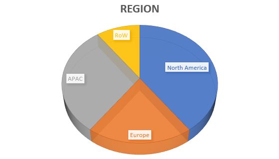
Commercial Building Lighting Controls is a booming business (Click Here to see Forecast). With so many different types of commercial controls systems on the market it’s hard to keep up with the latest and greatest. That’s our job here at Lite Rite Controls. Send us your plans and we can help you with great pricing and assurance that any system you are installing will work seamlessly.
*Only available with Eclipse Interface
As a controls and lighting company, Lite Rite Controls is often asked to bid jobs that have nLight as a commercial building’s Lighting Control Systems. For those of you not familiar with nLight, I have added a brief description below of both nLight and nLight Air.
nLight is a networked digital lighting control system that provides both energy savings and increased user configurability by cost effectively integrating time-based, daylight-based, sensor-based and manual lighting control schemes. nLight creates an unmatched level of distributed intelligence.
nLight Air is a secure, high-performance wireless platform designed for integration into various lighting controls applications that seamlessly connect both indoor and outdoor lighting systems to Smart Building Ready solutions.
Benefits Include:
- Easier installation – fixture embedded smart sensor remove guesswork, saving time and money
- Industry leading 5-tier wireless security architecture
- Energy savings with occupancy and daylight sensing — up to 30% additional energy savings
- Aids in meeting and/or exceeding state and local energy codes
- A scalable and upgradeable smart building ready solution
- Choose from a wide range of nLight AIR wireless enabled fixtures from Acuity Brands
Check out this nLight Video: https://www.youtube.com/watch?v=jXlGJvN9x4Q
Renpeng Zhang, a Lite Rite Controls employee and recent graduate from Long Beach State University with a BS in Electrical Engineering, recently attended training on Acuity nLight products. Renpeng has experience programming and designing many different commercial building control solutions currently on the market and I wanted to find out what his thoughts were on the nLight product.
Jerimiah Hubner, Lite Rite Controls (LRC): How did the nLight training go?
Renpeng Zhang (RZ): Yeah, it went really well. I liked that nLight is completely customizable. The training was very hands on, which I enjoyed.
LRC: That’s cool. Can you tell me about nLight’s customizable features?
RZ: Well, there are more customizable control features for commercial building control systems. One of the features is the “grace period” timing controls*. This controls how much time the occupancy/vacancy sensor takes before turning off lights or plug loads. Most products have a 10 second grace period. nLight allows for control over this option, which is important for the usability and comfort of tenants.
The second customizable feature that I thought was important was that up to 16 virtual buttons can be added to the nPOD GFX. This allows for greater scene and setting control.
LRC: Sounds like nLight has taken notice that usability and functionality are top priorities for tenants. What about EC’s and installation?
RZ: Contractors say that it is easier to build rooms with the nLight product because it is systematic with zones or channels. The electrician can install nLight in a single room, test it individually and ensure that it is functioning. If rooms will be added to the system, the EC can connect / integrate the rooms via the nLight Gateway or Eclipse. If the EC is also programming the system, nLight’s Sensor View software will be used. For less advanced and simple programming, nLight can be programmed with the nPOD GFX.
LRC: Can nLight connect with mobile devices?
RZ: Yes, but only with the Eclipse controller. This allows communication with the Eclipse interface on a secure web browser via PC, laptop or any other mobile device. This enables profiles for different rooms. Imagine there is a conference room that is mainly used for presentations. You could basically program a “presentation” scene or mode into the profile for that room and lights would automatically adjust. The possibilities are endless.
LRC: Thanks for sharing your experience with Acuity’s nLight product, Renpeng.
Want to learn more about nLight and nLight Air? Click Here
Commercial Building Lighting Controls is a booming business (Click Here to see Forecast). With so many different types of commercial controls systems on the market it’s hard to keep up with the latest and greatest. That’s our job here at Lite Rite Controls. Send us your plans and we can help you with great pricing and assurance that any system you are installing will work seamlessly.
*Only available with Eclipse Interface