How to replace LC&D relays
Blue Box LT panel with Dual Pole relays
A Blue Box LT master panel does not have the depth to support the extra height required on the dual pole relays.
Only a Blue Box Classic or GR2400 will be needed to support the dual pole relays if they need to exist in a master panel.
However, a Blue Box LT remote panel does have the depth to support the height required for dual pole relay.
Navigating the DTC on Blue Box
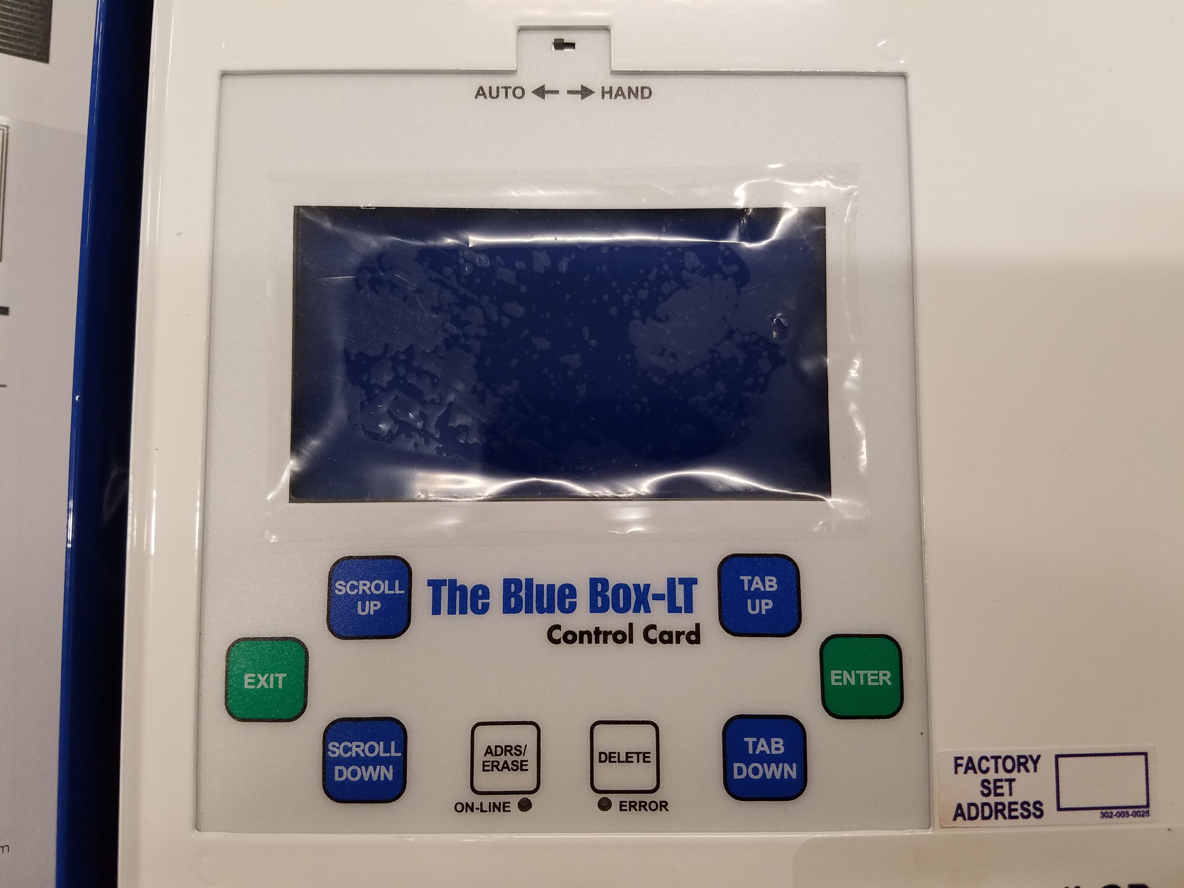
Tab Up & Tab Down
The TAB UP and TAB DOWN keys are used to move the cursor forward and backwards across the display. They change which parameter on the screen is selected.
Scroll Up & Scroll Down
The SCROLL UP and SCROLL DOWN keys are used to adjust the selected parameter. They are also used to override groups, copy switch programming, and disable or enable selected schedules. Scrolling up or down on a page number will bring you to the next page on the screen.
Enter/Exit
The ENTER button enters into the selected sub menu. It is also used to toggle loads from the manual override screen, and add loads into a switch or group. The EXIT button brings you back to the previous menu.
Delete
The delete key is used to delete groups and schedules.
Setting the Contrast
To set the contrast on the GR2400, hold the CONTRAST key, and then press SCROLL UP or SCROLL DOWN. To adjust the contrast on a Blue Box, there is a contrast adjustment screw on the back of the DTC.
Auto/Hand Switch
The Auto/Hand switch can be set to HAND to close all relays in the panel. This is useful for testing relays, and verifying line voltage is present on the relays. The panel must be in AUTO mode under normal operation.
General Photocell Programming
Photocells
PCC1 and PCC3
PCC1 & PCC3 cards are photocell input cards. A PCC 1 card is a single input card that cannot be digitally disabled and a PCC3 card is a 3 input cartally disabled. PCC cards read the light level from a 2-wd that can be digiire analog photocell, and communicate the reading back to the system controller. To program a PCC card, select PROGRAM SWITCH from the USER MENU and press ENTER. Select the ID# of the photocell card and PRESS ENTER (PCC cards will appear as ANALOG/DIGI in the PROGRAM SWITCH screen). You will see a list of triggers.
PCC cards are programmed using triggers. A trigger defines two things: The lighting levels at which the loads will turn on and off, and which loads are being triggered at those levels. To program a trigger, select a TRIGGER# and press ENTER. Here you can enter which loads are to be controlled by that trigger the same way you would enter loads into a Chelsea switch.
The mode of the TRIGGER will appear in the top right hand corner of the trigger screen. The default mode is MAINTAIN. If you press enter while the mode is selected, you can adjust the on and off triggering levels:
If you press SCROLL UP or SCROLL DOWN while ANALOG is selected, you can choose which input number on the PCC card the trigger is referencing. In the image above, input #1 on the PCC card is reading 32. TIME DELAY indicates how long the photocell must be beyond the triggering points before it will switch the loads. You can SCROLL UP or SCROLL DOWN on the on and off triggering levels to adjust them here as well.
Disabling PCC Inputs
On a PCC3 card, inputs 1-3 are disabled using triggers 11-13. If a load programmed to trigger 11 is ON, trigger 1 is disabled. If a load programmed to trigger 12 is ON, trigger 2 is disabled. If a load programmed to trigger 13 is ON, trigger 3 is disabled. This assumes triggers 11-13 are programmed in ON MODE.
Adjusting Input Sensitivity
Below each photocell input on a PCC3 card, is a dial that can be adjusted to change the sensitivity of that input. Turning the dial clockwise will decrease the sensitivity of the input to work better outdoors. Turning the dial counter clockwise will increase the sensitivity of the input to work better indoors.
Micropanel (iDIM/iDH) Photocells
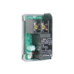
If an LC&D system uses a photocell hooked up to a MicroPanel, the photocell may only control loads from within that MicroPanel. The Micropanel photocell is a 3-wire photocell and it is wired to the control card as shown below:
MicroPanel Photocell Setup and Operation
If you have a DIM channel set to PC, and you press ENTER while PC is selected, you will see this screen:
You can SCROLL UP or SCROLL DOWN on IN1 here to select a different photocell input for that channel to reference. FADE UP and FADE DN are the amounts of time it will take for the dimmer to sweep along the full dimming range up and down respectively. START indicates the light level where the channel starts to dim. MID indicates that lighting level where the dimmer will output 50%, and OFF indicates the lighting level at which the channel will turn completely OFF. If the brightness is above the MUST Turn ON level, the channel will turn on regardless of the fade times. Time Out from Off is the amount of time after the dimmer has turned off before it will turn on again.
LC&D Groups Guide
Groups
Any relays that are going to be on a time schedule must be part of a group. When more than 8 relays are being added to a switch button, those relays must also be part of a group. Groups are useful when you have multiple switches that operate the same loads. You can assign a group to a switch or photocell, instead of having to assign every load individually. To create or edit a group, press ENTER on GROUP LOADS on the USER MENU. Select the group number you wish to edit, and press ENTER. You will a screen similar to this one.
Group Types
Momentary On
This is similar to On Mode. When a group is set to Momentary On, that group will turn on whenever it is triggered.
Momentary Off
This is similar to Off Mode. When a group is set to Momentary Off, that group will turn off whenever it is triggered.
Momentary Mix
This is similar to Mix Mode. When a group is set to Momentary Mix, the group can trigger some relays ON, and others OFF at the same time.
Maintain
A group programmed as Maintain will stay on as long as it’s ON command is held. On a switch, the button has to be held down for the load to stay on. This is also the correct group type to use for loads under photocell and time schedule control.
Maintain + Timer
This group type is made to be used in conjunction with time schedules. When a Maintain+Timer group is scheduled on, the auto off timer will be disabled, and the lights will stay on. Outside the hours of its scheduled times, the group will time out and shut off after being on for a certain amount of time. If you press ENTER while you have this group mode selected, you can adjust the value of the timer by entering into the SET TIMER sub-menu (default is 2 hours).
Maintain + Blink
This group type is the same as a Maintain+Timer group, except the lights will flash before timing out to warn the occupant. If you press ENTER while you have this group mode selected, you can adjust the number of minutes, prior to shutting off, the lights will blink. This setting is also adjusted under the SET TIMER sub-menu. A 2nd blink warning can be programmed here as well.
Overriding Groups
To override a group, select GROUP LOADS from the USER MENU and press ENTER. TAB DOWN and select the group you want to override. SCROLL UP to override the group ON. SCROLL DOWN to override the group OFF.
Deleting Groups
To delete a group, select GROUP LOADS from the USER MENU and press ENTER. TAB DOWN and select the group you want to delete and press the DELETE key. Press ENTER on ‘Yes’ to confirm.
Group Toggle
You cannot toggle a groups do not have a toggle mode. If you want to appear to toggle a group, you have to use 2 groups 1 group set to ON 1 group set to OFF with the same relays in them, a spare status relay, and the button 7 & 8 special functions.
Global Groups
Groups 17-32 are preprogrammed to be global for all multi-bus systems. This means they will activate universally across all system buses whenever activated on any single bus. To take advantage of this feature, the global group must be set up identically on all system buses.
How to program an LC&D schedule
Schedules
Schedules are used to set automatic on and off times for any relays inside an LC&D panel. They are also used to set up photocell schedules for the on-board photocell in a master Blue Box. To edit or view the existing schedules, select REVIEW SCHEDULE from the USER MENU and press ENTER. A column of schedules will appear on the left. What those schedules control will appear in the column on the right. The schedules (SCH 1, SCH 2…) contain the off and on times. The group to the right of a schedule, contains the relays that will turn on and off at those times. See the following screenshot:
Press SCROLL UP or SCROLL DOWN on a GROUP # or NO LOADS to change what group is controlled.
Schedule Types
Every Day
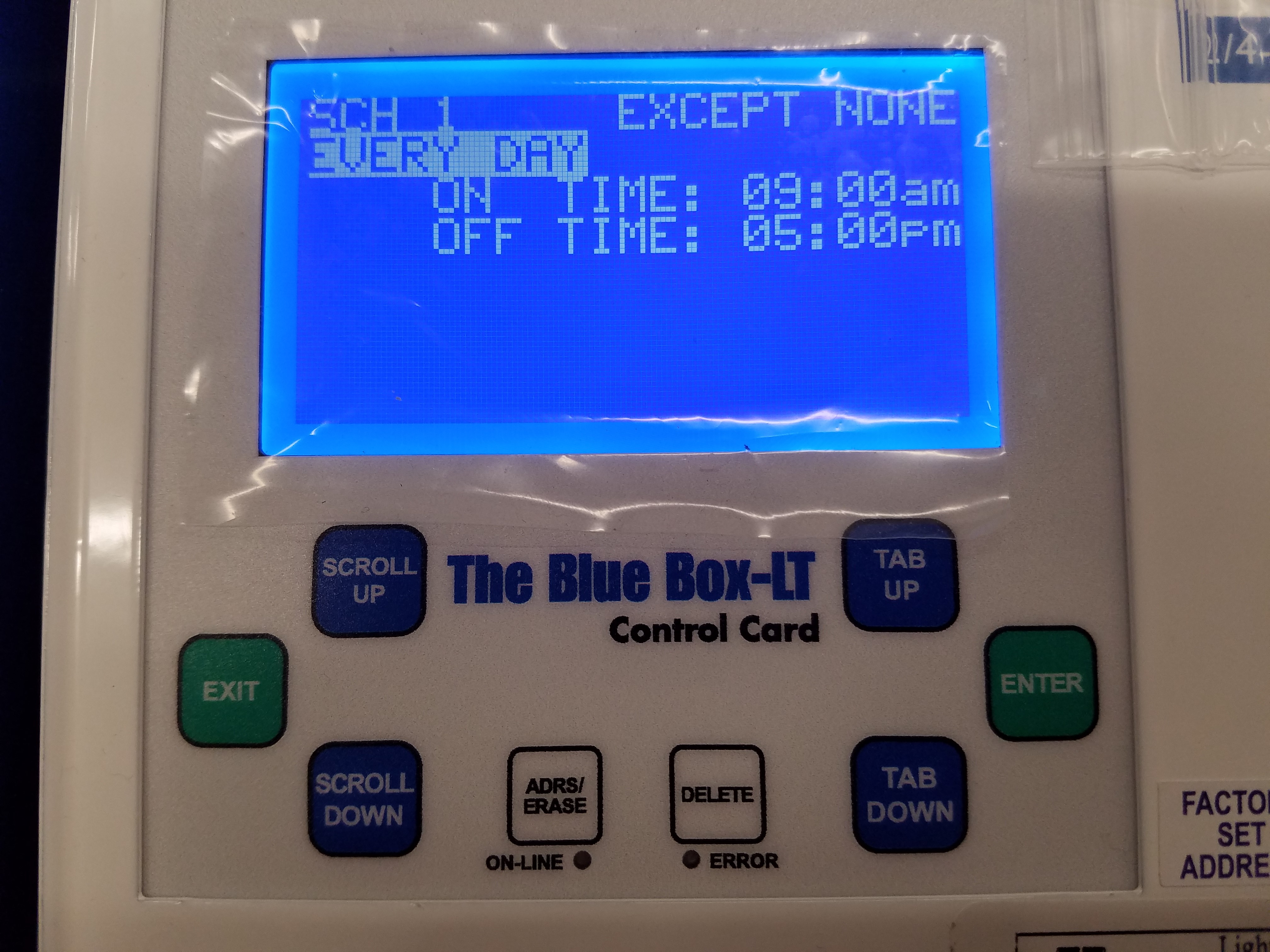
A schedule to set to EVERY DAY means that the schedule runs every day of the week, and does not change from day to day.
By Day
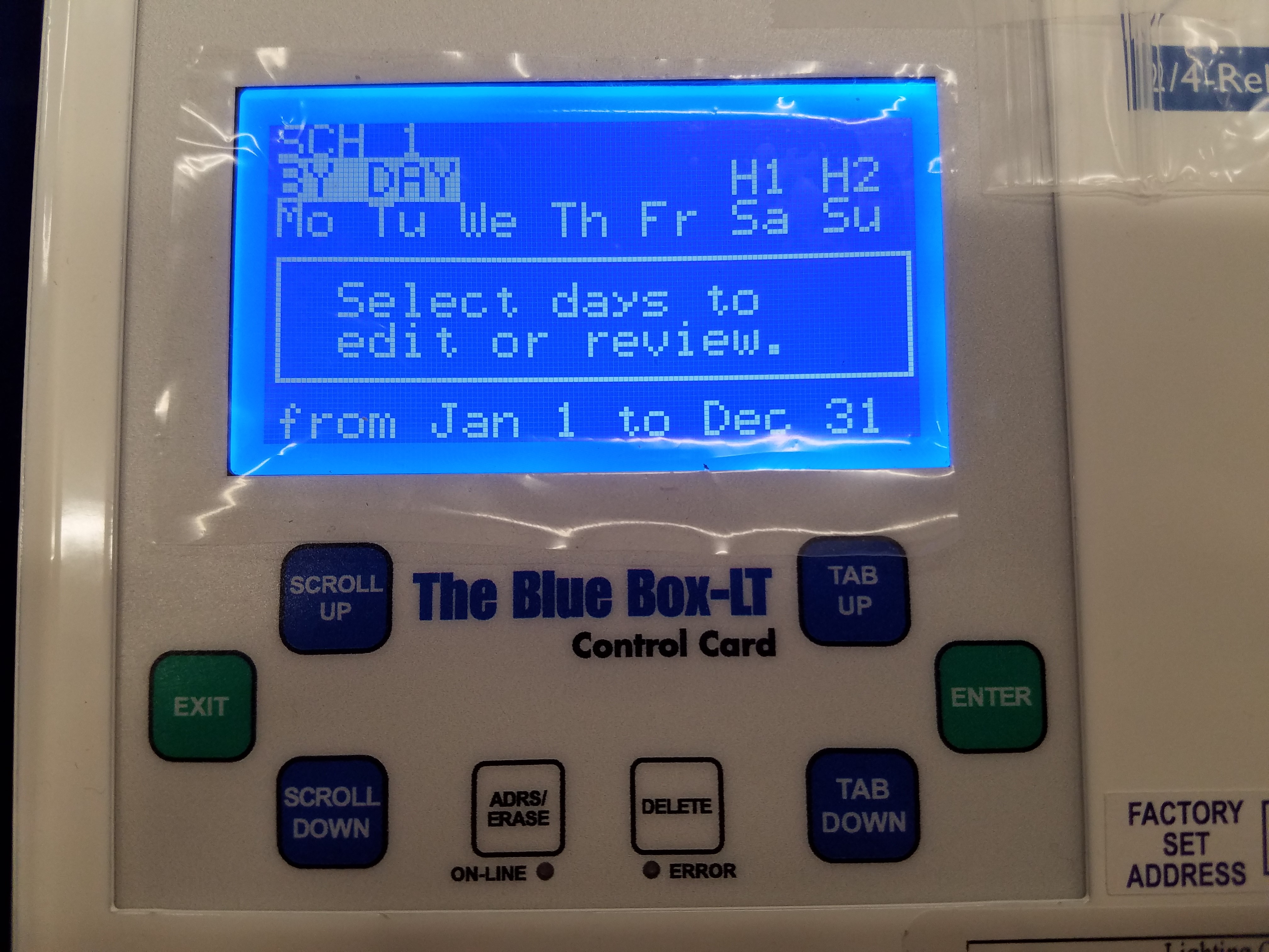
A BY DAY schedule is used when different on and off times are needed for different days of the week. Press ENTER on any day of the week to change the on and off times for that day. BY DAY schedules can also be set up to run within a certain range of dates. This range can be adjusted at the bottom of the BY DAY schedule screen.
Monday-Friday
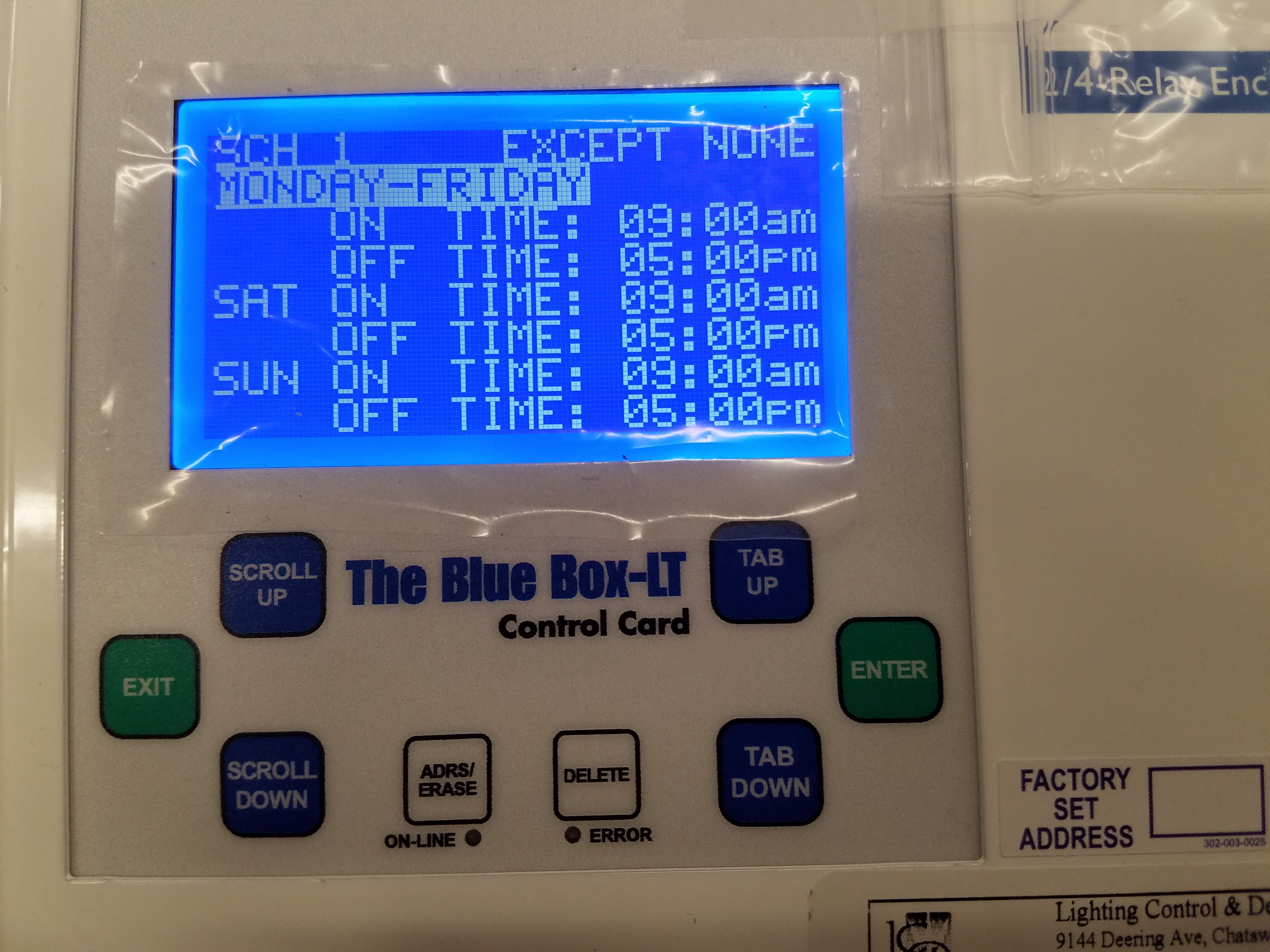
A schedule set to Monday-Friday runs the same schedule Monday through Friday, but allows you to program separate on and off times for both Saturday and Sunday.
Pressing SCROLL UP or SCROLL DOWN on the word TIME, changes control method of that timed event.
Schedule Control Methods
Time Based
When a schedule displays ON TIME, or OFF TIME, it is switching on or off its group at a particular time. This is the default control method for a schedule. The ON TIME indicates what time the schedule will turn its group on. The off time indicates what time the schedule will turn its group off. The time set on the controller is displayed on the start screen.
Photocell
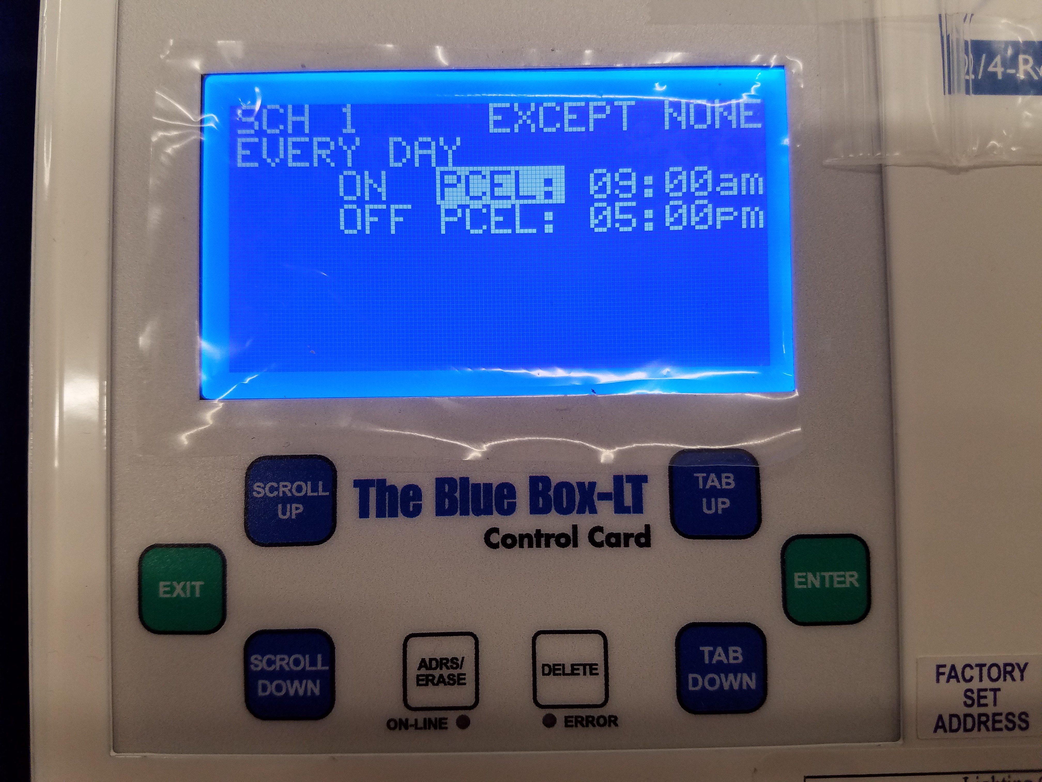
When a schedule displays ON PCEL or OFF PCEL, it is switching based on a photocell. The ON PCEL time indicates what time the onboard photocell, in a BlueBox, is going to start controlling the group. At the OFF TIME, the lights sweep off, and the photocell relinquishes control of the group. If you have the word PCEL selected, and you press ENTER, you will see this screen:
ANALOG1 shows the current value that the on board photocell is reading. TIME DELAY is how long the photocell must remain past the triggering levels, before actually switching the loads. ON WHEN LEVEL FALLS BELOW will turn the loads on when the lighting level read by the photocell is under the set value. OFF WHEN LEVEL RISES ABOVE will turn the loads off when the lighting level read by the photocell is above the set value.
Astronomical
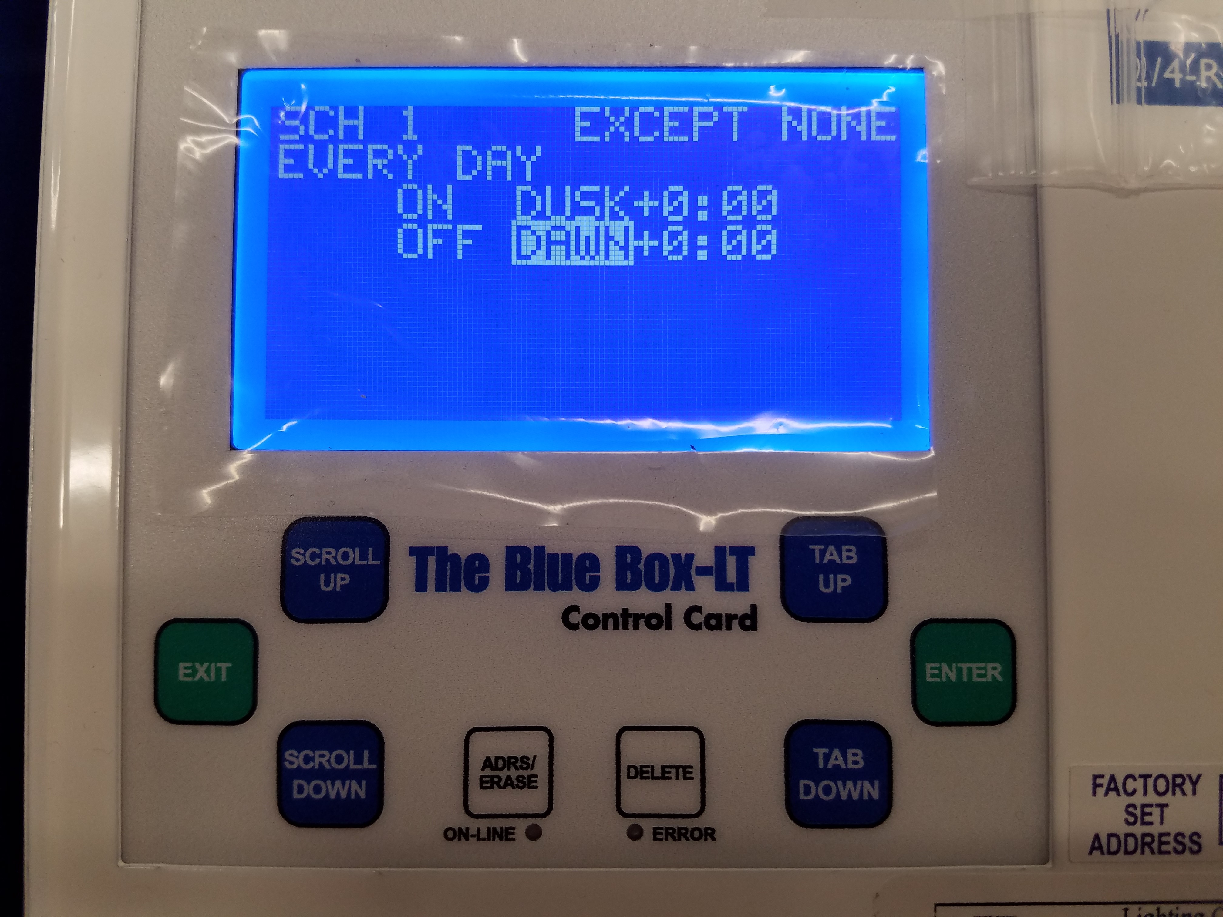
When a schedule displays ON DUSK, ON DAWN, OFF DUSK, OR OFF DAWN, it is switching its group according to an astronomical clock. Using this method, the controller will use the longitude and latitude entered in its SYSTEM OPTIONS, to calculate the DUSK and DAWN times. DAWN indicates the time that the sun sets. DAWN indicates the time that the sun rises. The times that the controller calculates dusk and dawn to be, will flash periodically on the start screen of the system controller.
Setting up Holidays & Exceptions
By default, schedules are set up with no exceptions (EXCEPT NONE). An exception is a day of the year, in which the schedule does not run. To set up an exception, the day you would like to exempt must be entered into a holiday list. To do this, enter into the SETUP MENU from the USER MENU. Select SYSTEM SETUP MENU and press ENTER, and then select EDIT HOLIDAYS and press ENTER. Enter into either holiday list. Pages 1 & 2 of the holiday list have predefined, commonly used holidays. Pages 3 & 4 have dates that you can adjust yourself. To make a day in the holiday list active, scroll on NO next to the day and change it to YES:
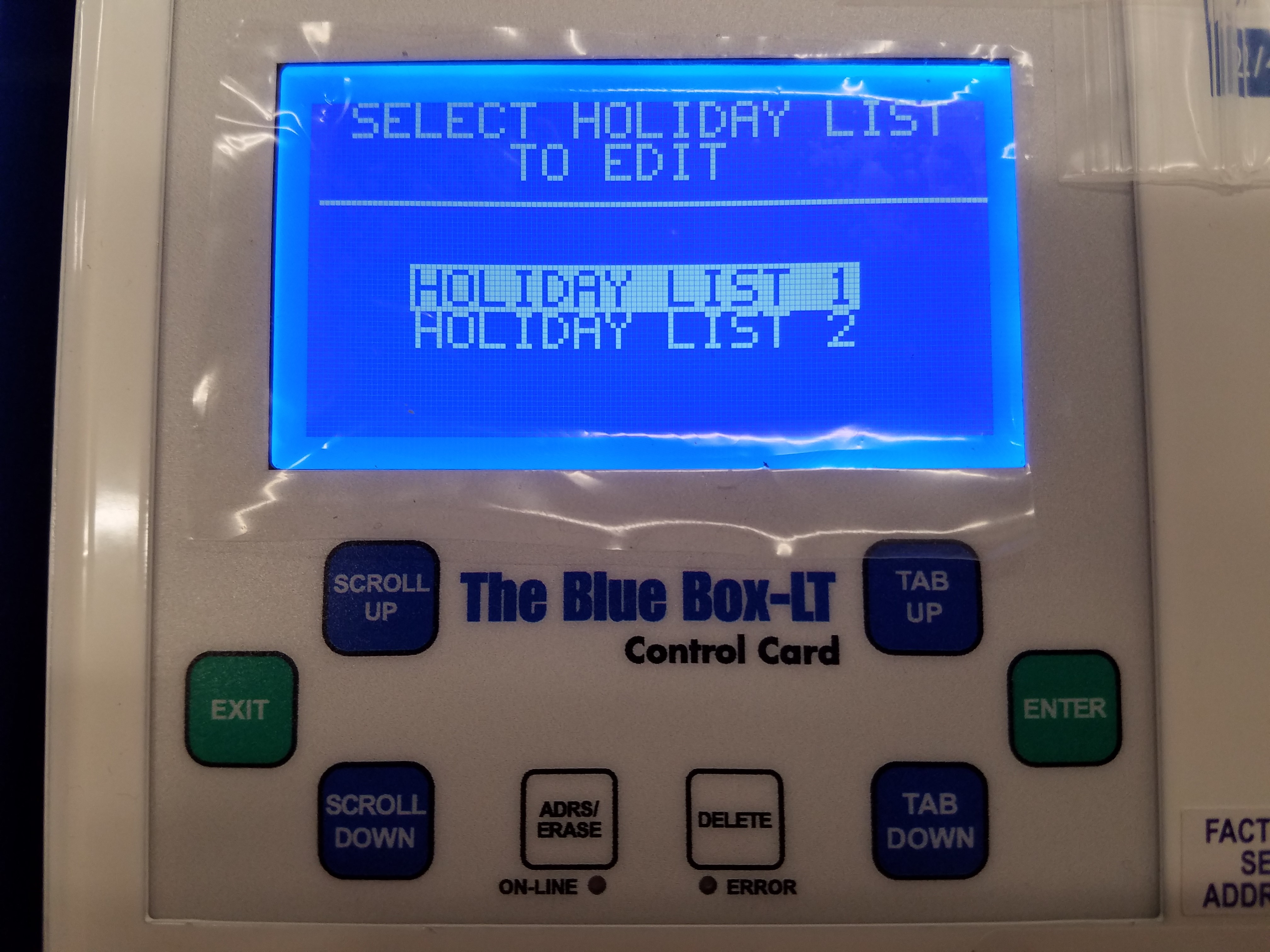
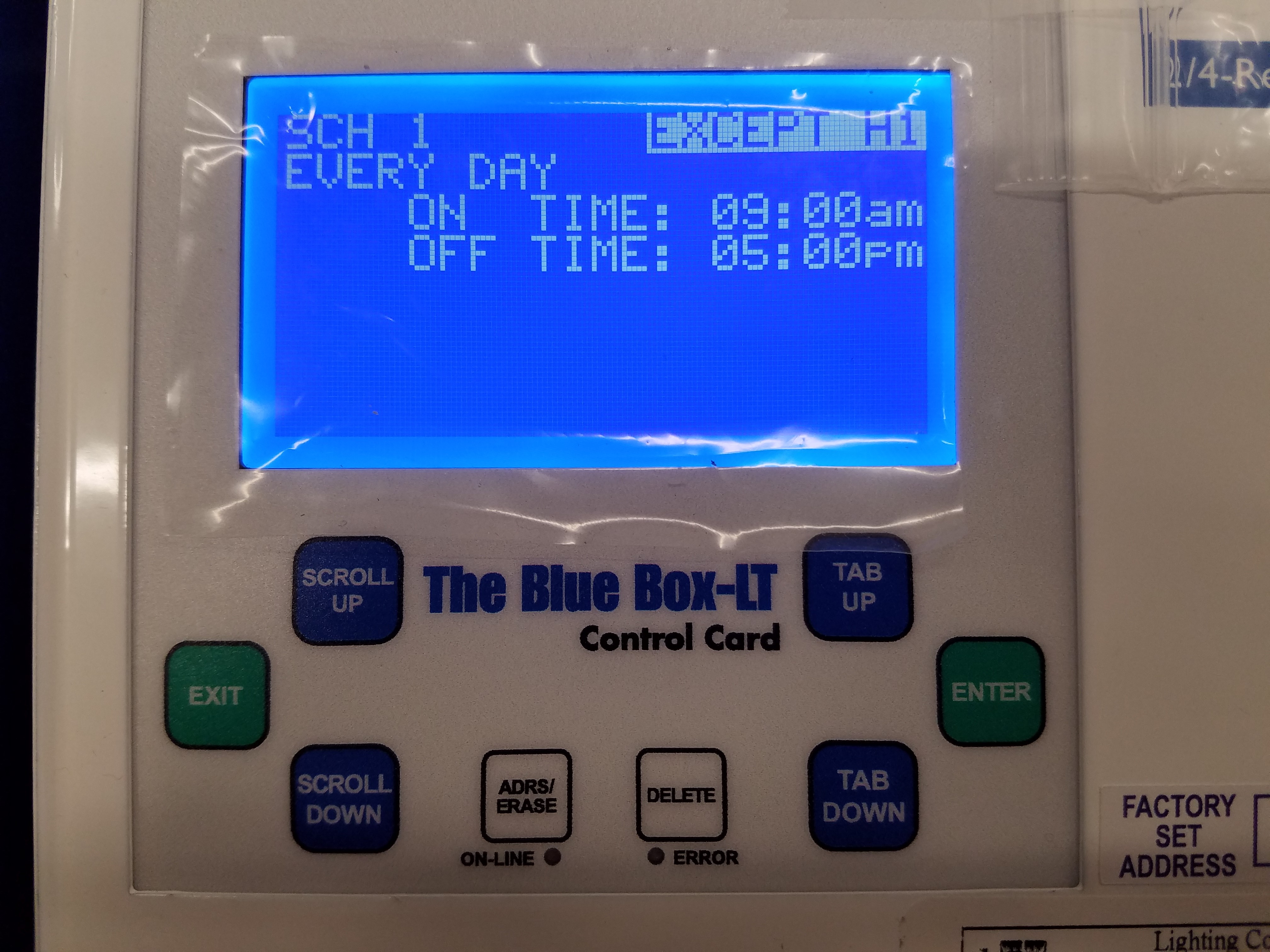
After you have set the day to YES in the HOLIDAY LIST, scroll on EXCEPT NONE in the schedule screen to change it to EXCEPT H1, EXCEPT H2, or EXCEPT H1+H2. Using EXCEPT H1 will exempt any active days in HOLIDAY LIST 1. Using EXCEPT H2 will exempt any active days in HOLIDAY LIST 2. EXCEPT H1+H2 will exempt activate days on both holiday lists:
Disabling or Deleting a Schedule
To disable a schedule, enter into REVIEW SCHEDULE from the USER MENU. Select the schedule you would like to disable and press SCROLL DOWN. The display will read ‘Disabled’ where the group normally appears to indicate the schedule is now disabled. To re-enable the schedule, select the schedule and press SCROLL UP.
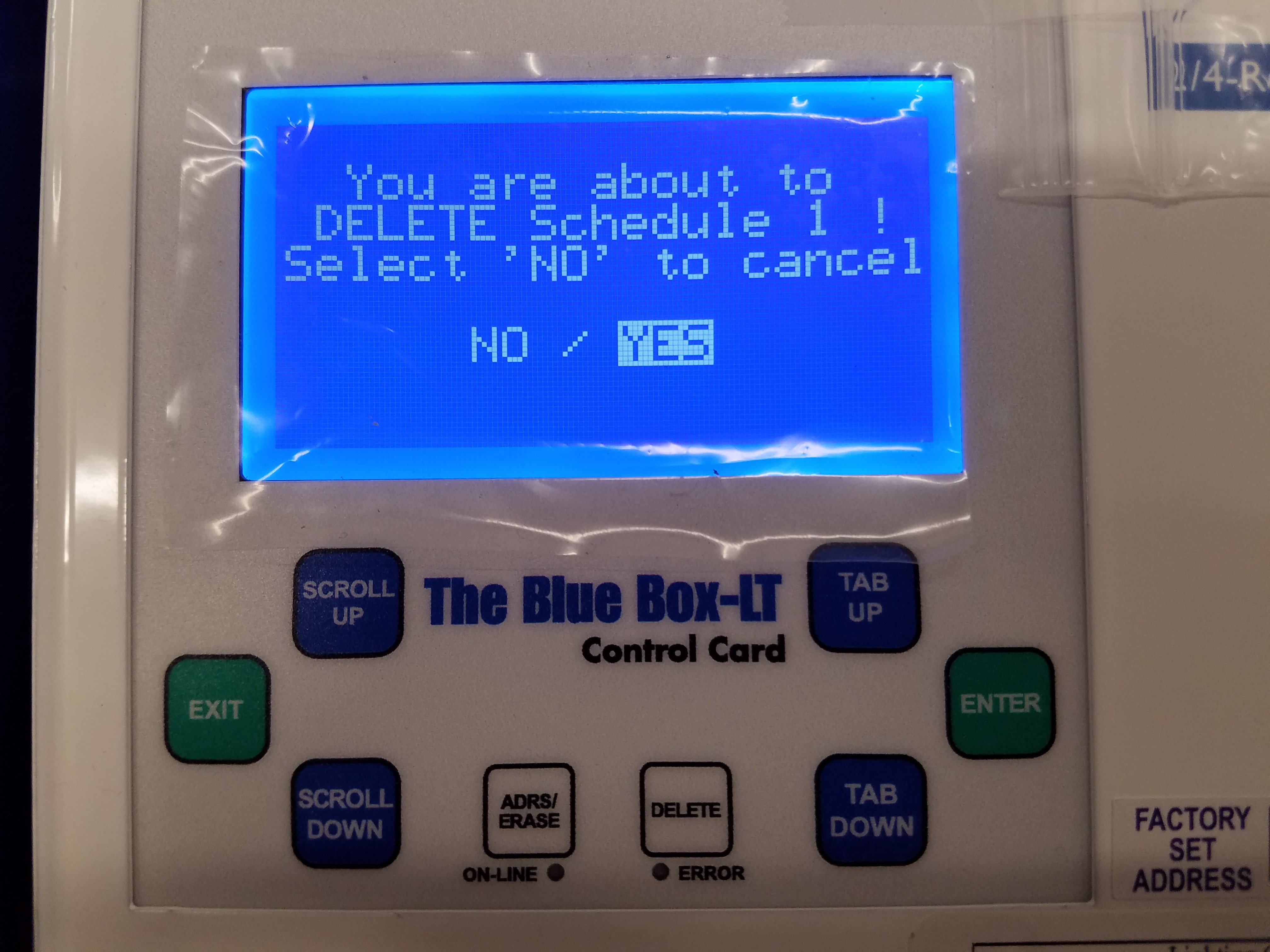
To delete a schedule, enter into REVIEW SCHEDULE from the USER MENU. Select the schedule you would like to delete and press the DELETE key. Press ENTER on ‘Yes’ confirm.
SnapLink Double Installation Guide
SnapLink Latching Relay Installation Guide